

Usually we use a battery level indicator along with rechargeable battery to monitor the voltage level. If the Lead Acid battery is deeply discharged below a particular voltage level ,Memory effect develops and the battery never attains full charge later. So it is necessary to monitor the safe voltage level in the battery. A 12 volt Lead Acid battery shows 13.8 volts in fully charged condition and it should not deep discharge below 9 volts. If it happens, immediate charging is required to maintain the health of battery.
So the most simple battery level indicator is an LED based circuit that lights an LED when the battery voltage is above the set level, say 9 or 10 volts and below that ,the LED extinguishes. But this kind of circuits has a drawback. The LED is always on,so it consumes around 2 volts which is a waste of power and the battery voltage drops even if the load is not running. So here is the solution to prevent that. This circuit lights the LED only when the battery voltage is below 9 volts. The circuit consumes very little power in the standby mode and as long as the battery voltage is between 9 and 13 volts, LED remains off. When the battery voltage drops below 9 volts, LED lights indicating the need for charging. You can also add a buzzer if audible warning is required. The circuit can be attached to any 12 volt battery like Inverter battery, Car battery etc.

How the circuit works?
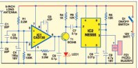
Two NPN transistors (T1 and T2) act as a voltage controlled switch for the LED. The transistor switch is controlled by a Zener diode. Zener diode is a special kind of diode that conducts only when it gets a voltage more than its rated voltage. For example, a 7.5 Volt Zener diode used in the circuit requires more than 8.5 volts for its smooth conduction. That means, the Zener requires + 1 or 1.5 volt excess than its rated value for proper conduction. Remember this when you select Zener value. For a 3.1 volt Zener, input voltage should be above 4 volts, for 5.6 V Zener input voltage should be 7 volts and so on.
So here the 7.5 volt Zener is connected between the positive rail and the 1K Preset (VR 1). Resistor R1 limits the current through the Zener. To the junction of R1 and VR1, the base of T1 is connected. So T1 will conduct when it gets base voltage from the Zener. When the battery voltage is above 9 volts, Zener conducts and T1 switches on. As a result, the collector voltage drops and it switches off T2 because the base of T2 will be at ground potential. So LED remains off. That means, the battery voltage is above 9 voltage and the battery condition is good.
When the battery voltage drops below 9 volts, Zener switches off. T1 also turns off. At this time, the collector of T1 becomes high through R2 and T2 gets base bias and it turns on. The LED connected to the collector of T2 turns on to indicate low battery level. VR1 adjust the exact point of the LED switching.
 Assembled circuit on Common PCB
Soldering side
How to set?
For proper setting ,you need a variable power supply. Connect it to the power supply and provide 9 volts. If LED is off, turn the wiper of VR1 till LED turns on. Then increase the voltage to 10 volts. LED will turns off. The circuit is now ready to use. If you do not have a variable power supply, use this method. Connect a new 9 volt battery and adjust VR1 till LED turns off. You can then connect the circuit to 12 volt battery. LED will turns off. You can also add a buzzer to get audible warning.

Bread board assembly- LED Off at 11.8 Volts

Bread board assembly – LED on at 8.7 volts
Note: In the Prototype, low watt Zener and Resistors are used. If the battery is high current one, use 1 Watt Zener and 1 Watt resistors. You can also use higher value resistors for other levels of battery voltage indication. For example, use 9 volt Zener for 10 volt indication and 10 volt Zener for 11 volt indication.


Very Useful Circuit. Sir is this circuit tested by EFY labs? Sir I am in need of such a circuit as I am building your another circuit “Hybrid Solar Charger”, published in EFY September 2013 issue. The “Hybrid Solar Charger” uses 12V 7Ah Battery. Sir Can you provide me the link to the circuit “Mobile Charger using 12V Battery”(Tested at EFY labs)?
This circuit is designed for the blog. See photos of the construction and testing. Hybrid Solar charger is my circuit published in EFY.
0 Pingbacks
Comments are closed.