
Generally a Fuse is added in the power supply positive of many DC operated devices to protect them from high voltage surges. But when the device fails, we have to check the fuse to see whether it is good or blown. We can add a simple circuit to show the status of Fuse. The circuit can be hooked to the output of the power supply. Here three simple Blown Fuse Indicator circuits are given.
Blown Fuse Indicator 1.
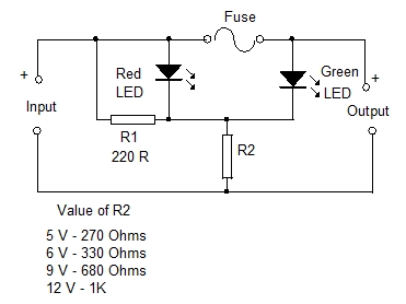
A Bicolour LED is used to give two status. Fuse Ok and Blown fuse. A Common Cathode type Bicolour LED is used here. It has a Green and Red LED inside with separate anodes and a common cathode. Green half of the LED has only one series resistor R2 while the Red half has two resistors R1 and R2. So when the fuse is intact, Green LED only lights because it gets more current than Red LED. When the fuse blows, Green LED turns off and Red LED lights. So a single LED gives two colour indications. In the place of Bicolour LED, Red and Green LEDs can also be used.
Value for selecting R2 for different voltages is given as table in the circuit diagram.
Blown Fuse Indicator 2.
This is more simple circuit having only one LED and two resistors. When the fuse is intact, LED glows bright because it gets more current through R2. When the fuse blows, LED turns dim since gets less current only through the high value resistor R2.

Value for selecting R2 for different voltages is given as table in the circuit diagram.
Blown Fuse Indicator 3.
Here an LED and a Diode are used. When the fuse is intact, LED remains dim and when the fuse blows, LED turns bright.

Value for selecting R1 and R2 in different voltages is given as table in the circuit diagram.


COMMENTS FROM VISITORS