
 Joule thief circuit is a self oscillating voltage booster circuit that gives high volt from low volt, say 3 volt from 1.5 volt. So by exploiting this property, we can light a 3 volt LED using 1.5 volt pen cell or charge a mobile phone from 3 volt solar cell or two 3 volt pen cells. It is called as “Joule thief” because it is stealing energy or joules from the battery. Let us design the Joule thief circuit.
You need the following to make the Joule thief circuit
1. Ferrite core
2. Two colour hookup wire
3. 1K resistor
4. Medium power NPN transistor like CL 100
5. Battery Holder
6. 3Volt LED
7. 1.5V Pen cell
How to make the Toroid transformer?
Toroid transformer is made by winding copper wire on a circular ferrite core. Take two colored hook up wires and wind 10 turns. The ends on one colour wire can be used as Primary and the other as secondary. No problem, you can use any wire as primary or secondary but the connections should not interchange. Fig.1 shows the Toroid transformer after winding.
Fig.1

How Joule thief works?
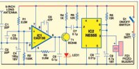
Fig.2
Fig.2 shows the completed Joule thief circuit. It is the basic design. The circuit works rapidly by switching the NPN transistor T1. Initially, current from 1.5 V cell begins to flow through resistor R1 (1K ), secondary winding, and base-emitter junction of T1 ( CL 100). This causes T1 to begin conducting collector current through the Primary winding. Since the two windings are connected in opposing directions, this induces a voltage in the secondary winding which is positive (due to the winding polarity,) which turns the transistor on with higher bias. This self-stroking or positive-feedback process almost instantly turns the transistor on as hard as possible, making the collector-emitter path look like essentially a closed switch. With the primary winding effectively across the battery, the current increases at a rate proportional to the supply voltage divided by the inductance.
Fig.3 shows the Joule thief circuit for charging the Mobile phone battery. Mobile battery is rated 3.6 or 4.5 volts, so around 6 volts is needed for charging. The circuit gives 6 volts output from a 3 volt Solar cell or two 1.5 volt pen cells. Basic working of the circuit is explained above. Some additional components are added for smooth charging. C1 removes transients from input voltage. Zener diode ZD regulates the output voltage. Diode D1 prevents back flow current from the battery under charge. Capacitor C1 act as a buffer for charging current.
Fig.3


COMMENTS FROM VISITORS