
 Save energy by installing an Automatic lighting system in your home. Connect the external lights to the system, so that it turns on the lights in the evening and turns off in the morning. No daily switching is needed and, it will light the premises of home even if nobody is there. It is too small and can be enclosed in a small plastic case.
The circuit has two sections. Power supply and a light controlled switch
Power supply
To make the unit compact and cost less, a Transformerless power supply is used. It drops the 230V AC to a low volt AC which is rectified and smoothed to DC. Here is the working principle of the Transformerless power supply.
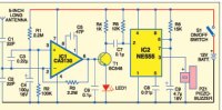
Capacitor C1
It is meant for dropping the high volt AC to low volt AC. 225 J 400 V capacitor is used which can deliver around 60 mA current to the circuit.
Resistor R1.
It is the 10 Ohms 1Watt resistor that reduces the inrush current at switch on.
Resistor R2
This is the Bleeder resistor to remove the stored current from the Capacitor C1 when the circuit is removed from the mains. Capacitor C1 stores very high volt and it gives a fatal shock even if it is removed from the mains. So the bleeder resistor is a must for the Transformerless power supply.
Diode Bridge
Four IN4007 diodes form a Full wave rectifier bridge that converts the low volt AC from the capacitor to DC.
Capacitor C2
This is the Smoothing capacitor to remove AC ripples from the rectified DC.
Resistor R3
A 47 Kilo Ohm resistor is used for the Zener to restrict current through the Zener.
Zener Diode
10 V 1 W Zener diode (ZD) is used to regulate the DC voltage to 10V for the circuit.
Capacitors C3 and C4
Both remove transients and noise from the power supply. So well regulated 10 Volt DC will be available for the Switching circuit.

Click image to get enlarged view
Switching Circuit
It comprises Complementary transistor T1, T2, LDR, and an Optotriac and a Triac .
Complementary Transistor
BC 547 (T1) and BC 557 (T2) works like this. When T1 is off, T2 will also be off. When T1 conducts, T2 also conducts.
LDR
Light Dependent Resistor (LDR)is used as the light sensor. It is a kind of variable resistor and its resistance is based on the intensity of light falling on it. That is, in dark, it offers very high resistance of around 10 Mega Ohms and in light; the resistance reduces to few Ohms.
Optotriac
MOC 3021 Optotriac is the device that encloses an LED and an Optical Triac. When the LED inside lights, Triac in the Optotriac conducts. LED in Optotriac works off DC, while its Triac works of AC.
Triac
BT 136 Triac is used to drive the load such as Bulb, CFL, Tube light etc. It works off 230V AC. When its Gate gets a positive voltage, it conducts and current flows through its M2 and M1 pins to drive the load.
Working
Working is fully automatic depending on the light falling on the LDR. During day time, LDR has less resistance and it conducts. This takes the voltage from the base of T1 to ground. As a result T1 remains off. At the same time T2 also remains off since its base is held high by the voltage through R4. LED in the Optotriac remains off since there is no collector voltage from T2. Load also remains off since the Triac is in the Non conducting mode.
During evening, sunlight reduces and LDR’s resistance increases. This gives sufficient base bias to T1 and it conducts. When T1 conducts, it pulls the base of T2 to ground and T2 turns on. LED in the Optotriac lights and Triac BT 136 starts conducting. Lamp then turns on. In the morning, the condition reverses and the lamp turns off.
VR1 is the preset or Pot that adjusts the sensitivity of LDR at the particular light level around 6 p.m. Use a 22K Volume control (Pot) so that, the sensitivity of LDR can be adjusted externally as per the requirement.
Setting
Fix the unit in a place where sunlight is available. Rain water should not fall on the unit. Connect the load with the circuit. Light should be away from the LDR, otherwise, it will cause false triggering and flickering of lamp.
Caution: This circuit is extremely dangerous if handled carelessly. It carries lethal high voltage that can give a fatal shock. So do not touch or trouble shoot the circuit when it is connected to mains. Enclose the circuit in a Shock proof case. Build this circuit only if you are competent to handle high volt circuits.


COMMENTS FROM VISITORS